CRC-SO-5000BMW is a third-party adapter set for fitting the xSystem to the BMW S1000XR models. It uses a novel approach to clamp the Scorpion Dual Injector in place and offers additional parts for route tubing and reservoir location under the seat.
BMW S1000XR (2020 onwards)
Scottoiler step-by-step fitting instructions
Preparation
- Tools needed: T25 & T40 Torx drivers
- Drill with 10.5mm and 2.0mm bits
- Crosshead screwdriver.
Note: References to "Parts" refer to the standard Scott oiler kit.
|
Phase 1: Disassembly & Access
- Remove the seat.
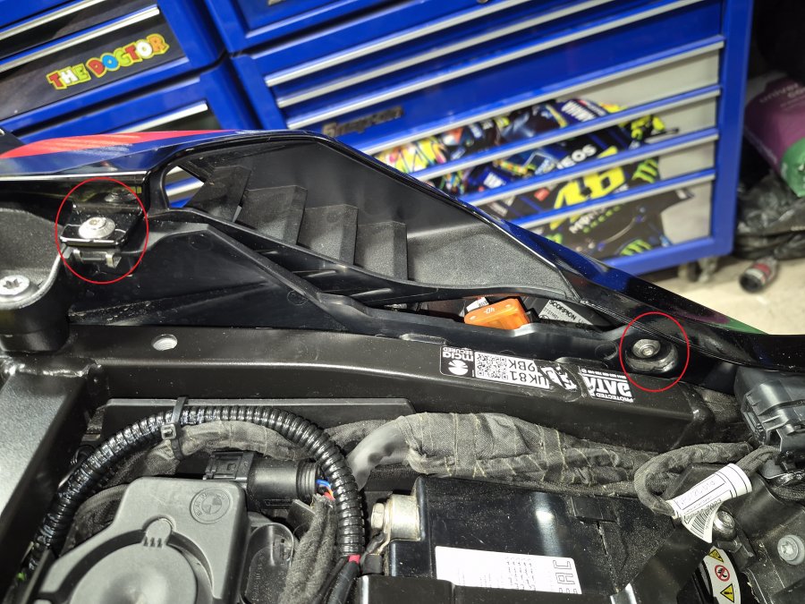
- Remove the left-hand side panel by unscrewing the two T25 Torx bolts. (Picture 1)
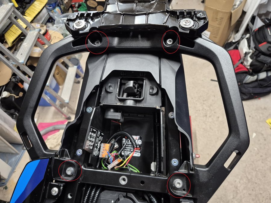
- Detach the grab rail by removing the four T40 bolts securing it to the subframe. (See Picture 2)
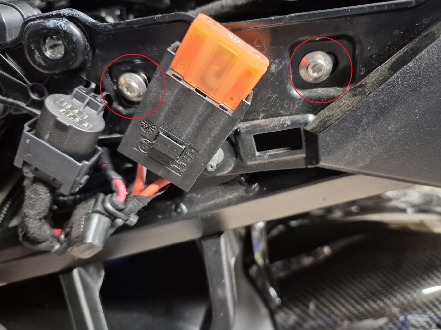
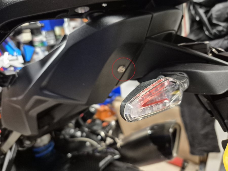
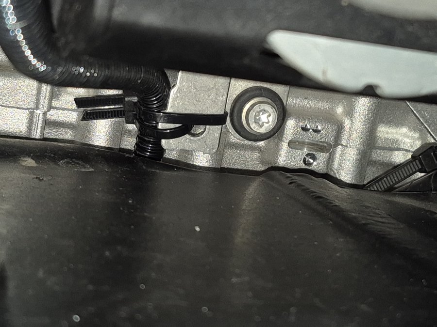
- Remove the subframe cover by unscrewing the three T25 Torx bolts and carefully unclipping the three electrical connectors. (See Pictures 3 & 4)
|
|
|
Phase 2: Reservoir & Main Routing
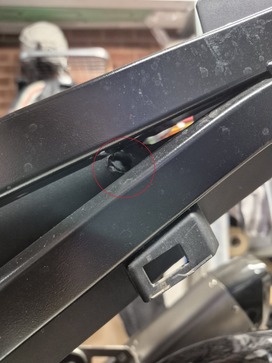
- Drill a 10.5mm hole into the plastic between the two subframe bars.
CAUTION: Manually move the wiring behind the plastic out of the way before drilling. (See Picture 5)
- Assemble the pipework: Feed the clear plastic pipe into the black corrugated protective pipe.
- Connect the reservoir: Feed the pipe assembly through the drilled hole. Attach Part 15 (adapter) to the clear pipe, then connect it to Part 1 (Reservoir).
- Mount the locking base: Secure Part 2 (Locking Base) to Part 1B (Storage Unit) using two M5 x 22mm bolts, washers, and Nyloc nuts.
Tip: Test-fit the reservoir first to ensure the base is facing the correct way up.
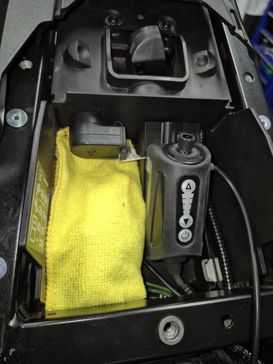
- Secure the storage compartment: Peel the backing from the double-sided tape and firmly press the unit to the left side of the compartment. (See Picture 6)
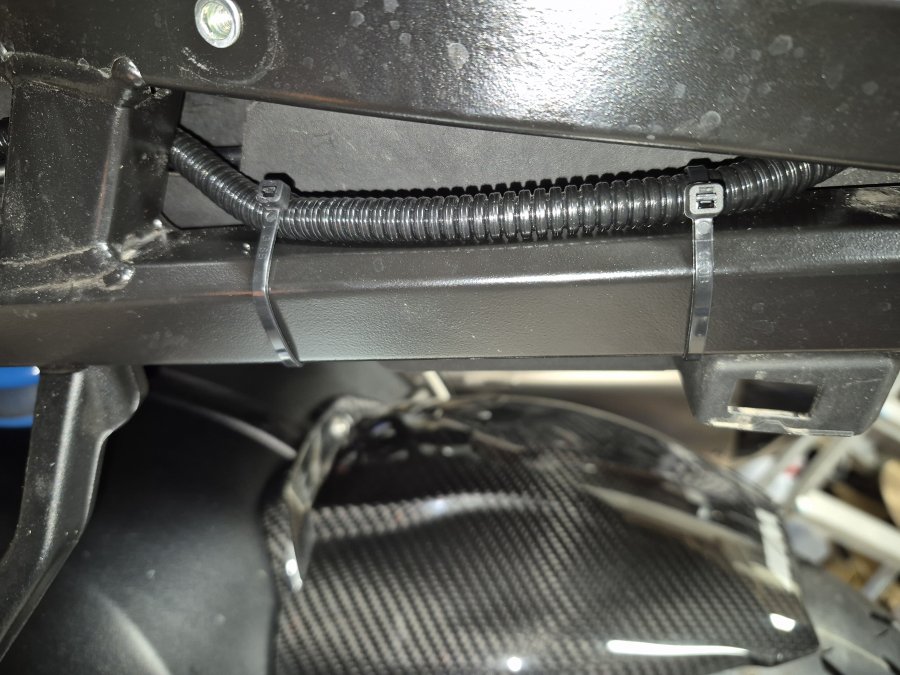
- Route the piping: Feed the pipework down the subframe and secure it using cable ties. (See Picture 7)
|
|
|
Phase 3: Swingarm & Feed Pipe Installation
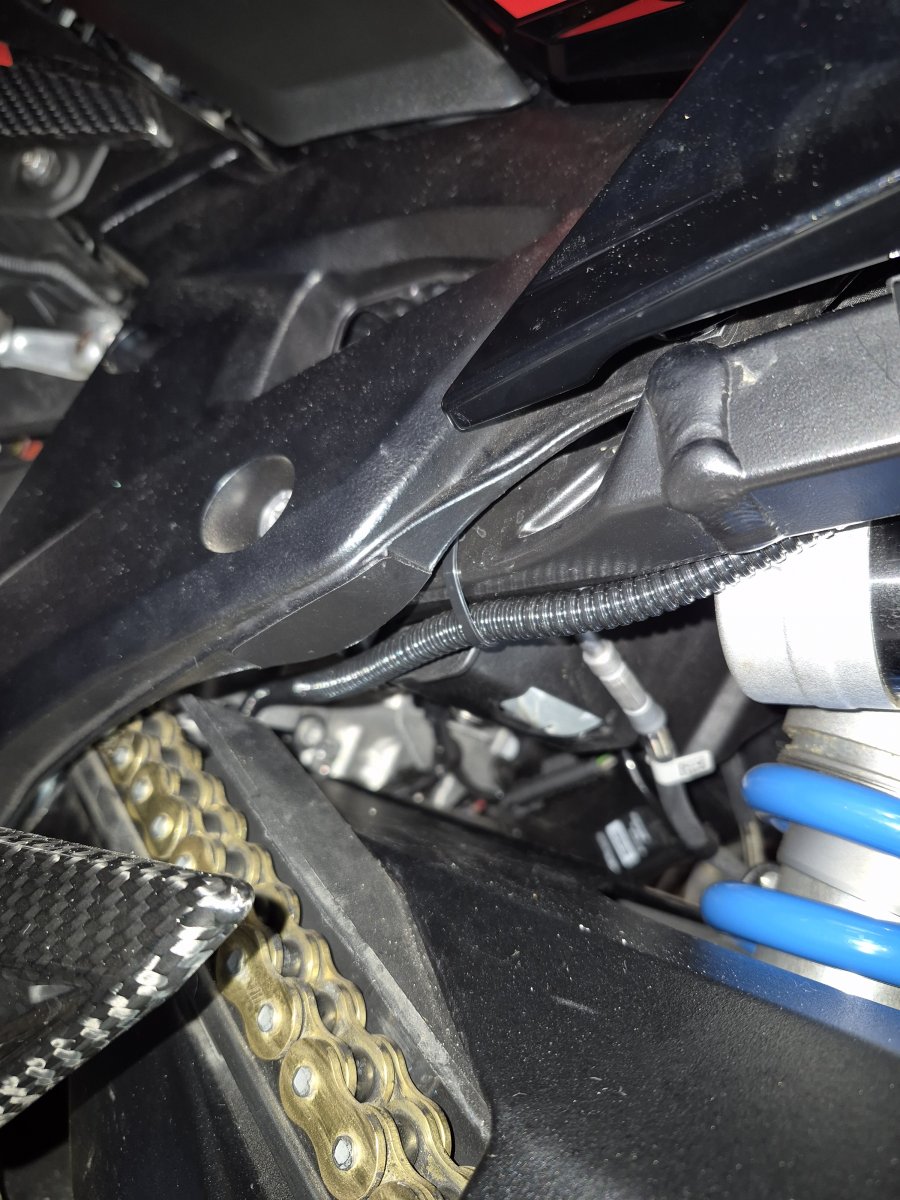
- Route to the swingarm: Run the pipe toward the swingarm and secure with cable ties. (See Picture 8 and 9)
- Prepare the swingarm cover:
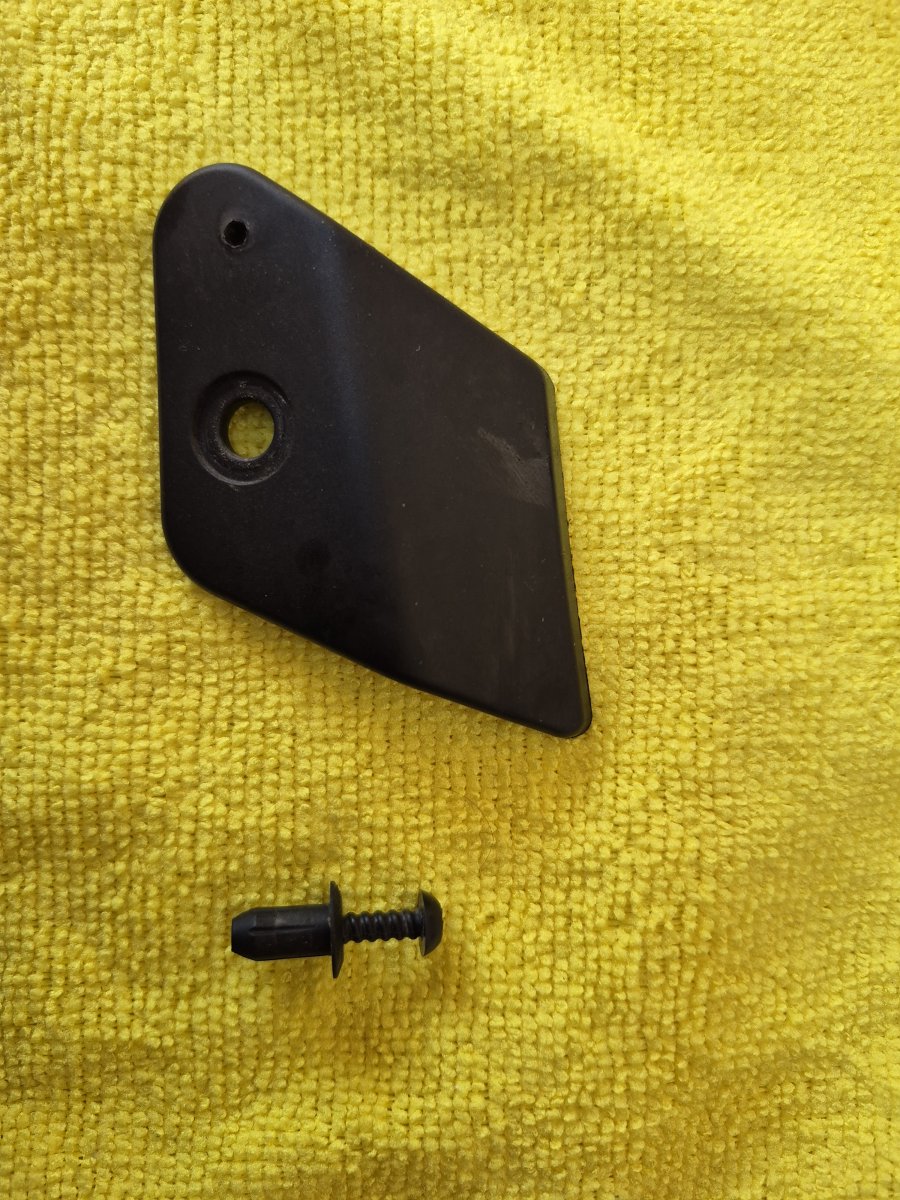
- Remove the plastic cover (secured by one crosshead screw).
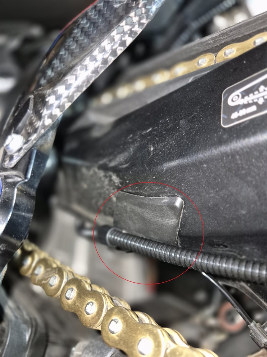
- Locate the plastic pin next to the screw hole and drill a 1.5mm hole into it.
- Reinstall the cover.
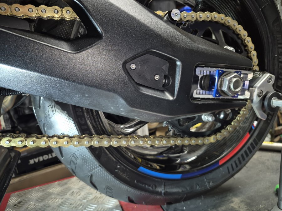
- Secure the feed pipe: Place the supplied P-clip around the feed pipe and screw it into the newly drilled 2.0 mm hole using the provided crosshead screw. (See Picture 10)
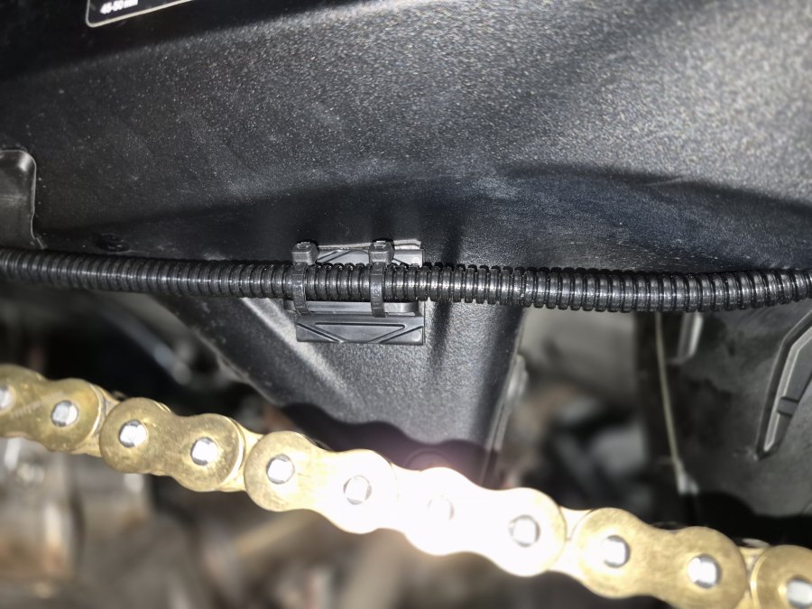
- Mount the tab: Clean the area with the provided wipe. Attach Part 11 (Mounting Tab) and secure the feed pipe to it with two cable ties. (See Picture 11)
|
|
|
Phase 4: Final Assembly & Alignment
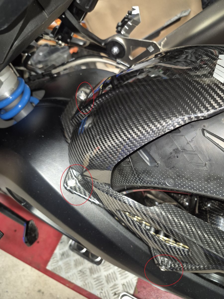
- Access the inner swingarm: Remove the four T25 Torx bolts from the rear hugger. (See Picture 12)
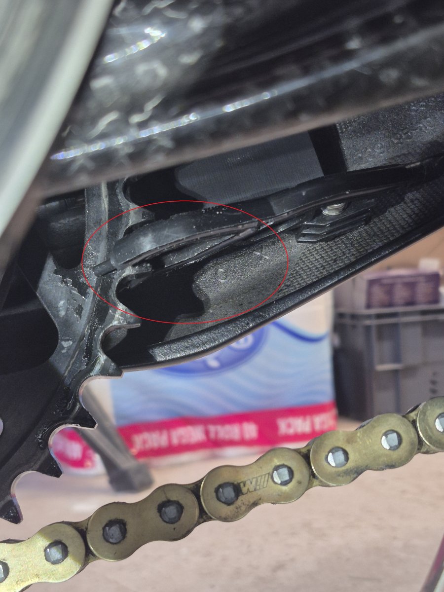
- Install the rear plate: Insert an M5 x 20mm bolt through the rear hole of Part 2B (Swingarm Unit), pass it through the swingarm, and secure Part 3B (Rear Plate) with a washer and Nyloc nut. (See Picture 13)
- Mount the Scorpion Feeder:
- Insert an M5 x 45mm bolt through the front hole of the unit, through the rear plate, and then through the Scorpion chain feeder.
- Secure with a washer and Nyloc nut.
WARNING: Do not overtighten, as this will damage the Scorpion feeder.
- Final Connection: Cut the oil feeder pipe to the required length and attach it firmly to the Scorpion feeder.
|
|
|
Final Check & Setup
Once physical installation is complete, follow the steps to activate and verify the system on the Scott oiler instalation manual
|
|