


Multistrada 1200 & 1260 (2015 - 2020)
Product Compatibility
- vSystem
- xSystem
- eSystem
- Traveller Expansion Bag
- Scorpion Dual Injector
- Magnum HCR
vSystem Installation
Step 1 - Find a vacuum source
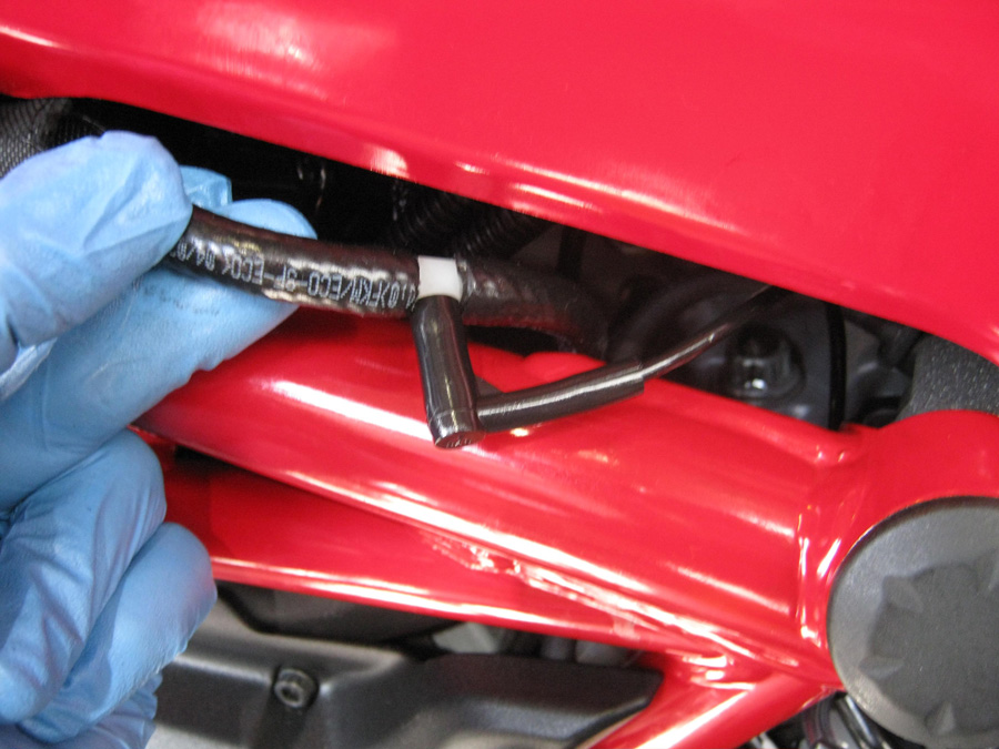
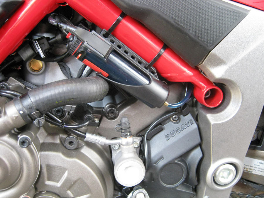
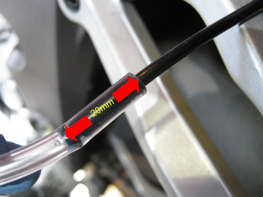
There is a vacuum pipe from the inlet tract on the cylinder head to the EVAP purge valve. You can read more about the EVAP System and how to identify the correct vacuum pipe here. Cut this pipe and insert the 4mm Tee connector, and push the vacuum damper elbow onto the third leg of the tee.
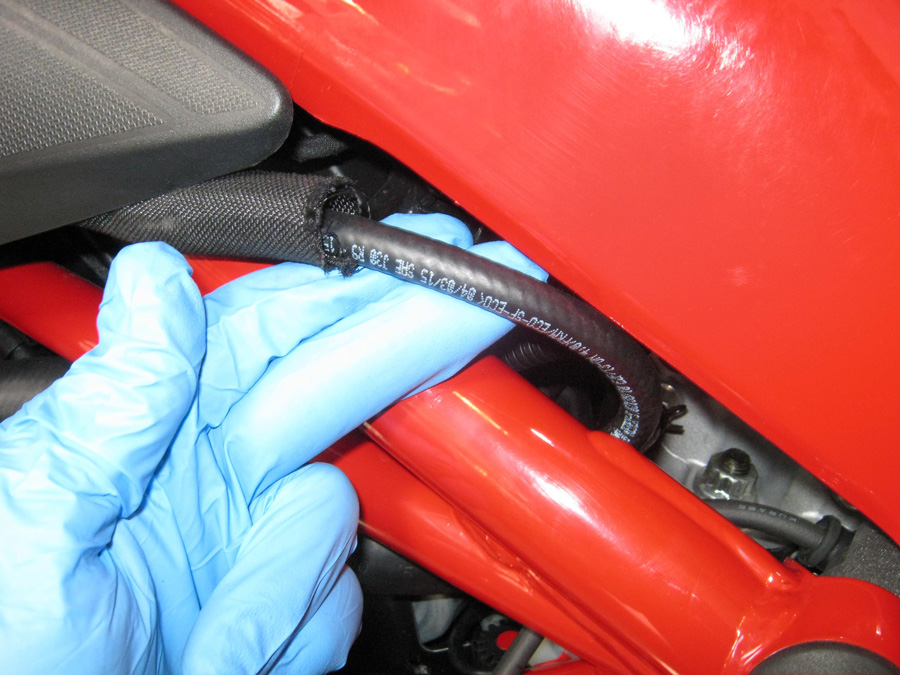
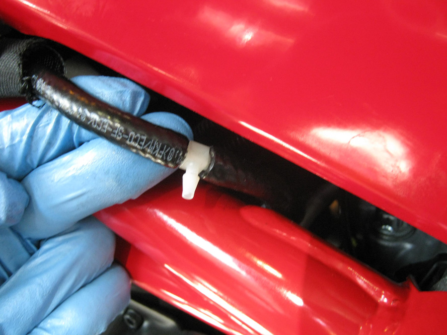 Cut and insert T-Piece. Then push the vacuum damper onto the third leg of the T-Piece.
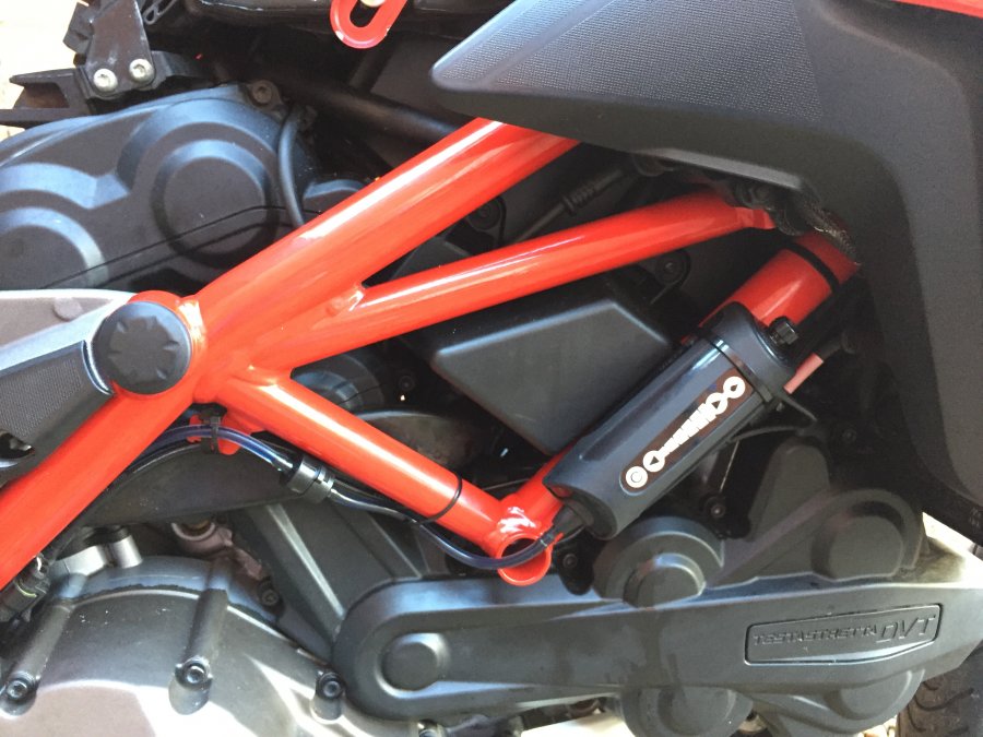
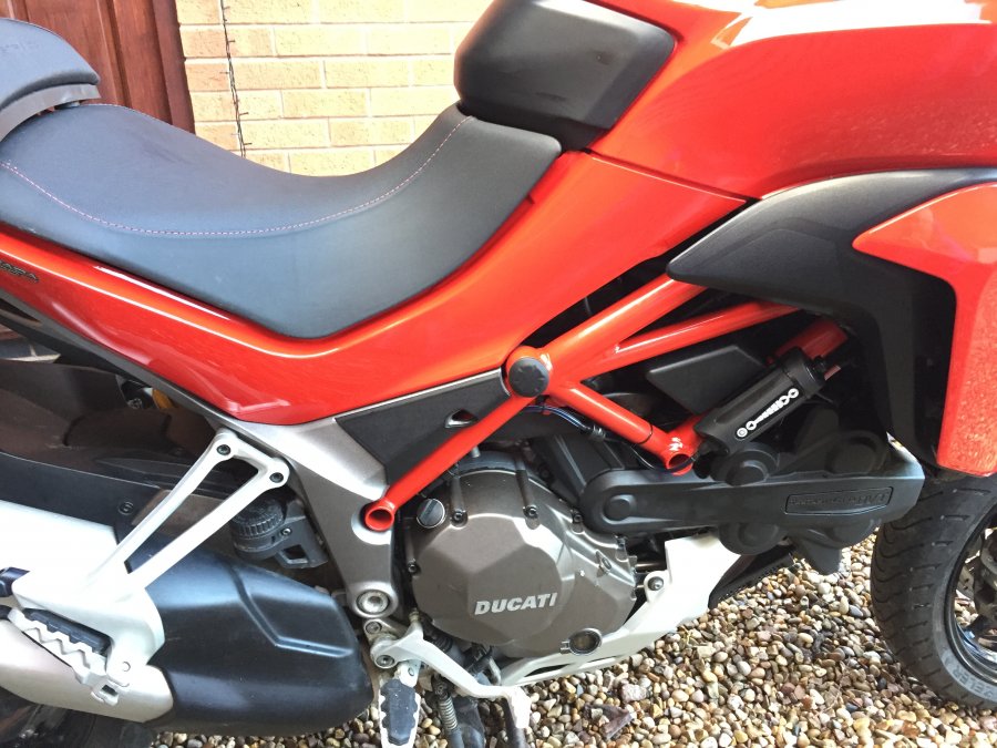
Step 2 - Find a place for the reservoir
The reservoir can be mounted under the seat or on a frame spar. Ensure that the top of the reservoir is at least slightly raised (ideally above 15° from horizontal) to maximise the available range.
Step 3 - Mount the dispenser and connect the system
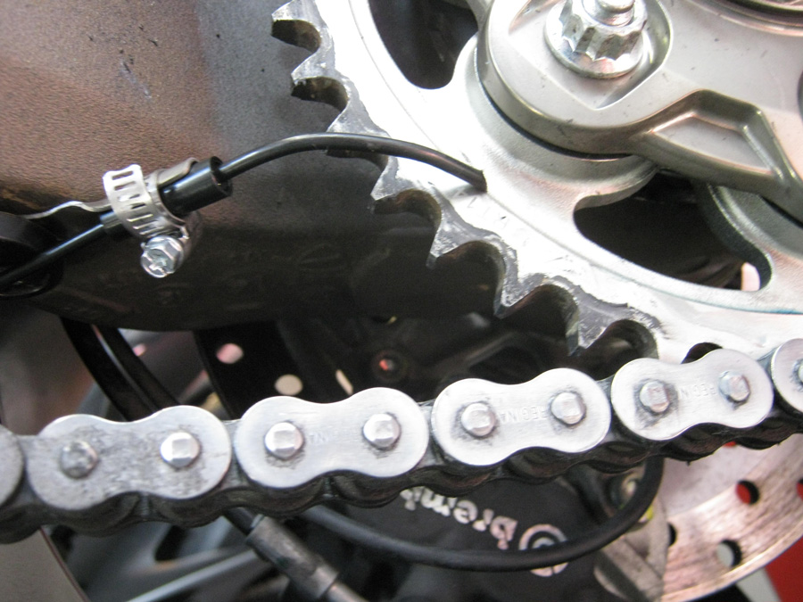
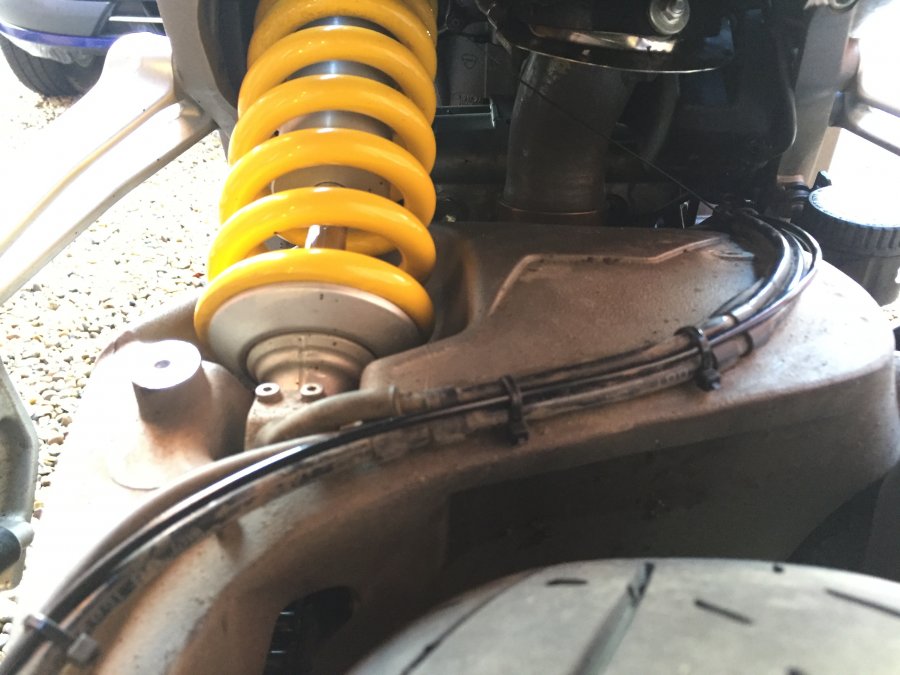
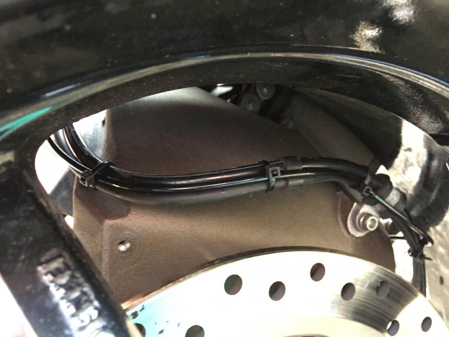
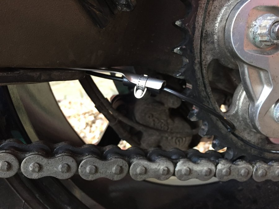
A dispenser can be made from vacuum tubing using the small dispenser plate and clip. The tubing can be routed with the rear brake line. For further information see our easy step installation guide - Dispenser Positioning. The curved nib should feed the outside face of the sprocket, with the slash cut facing outwards.
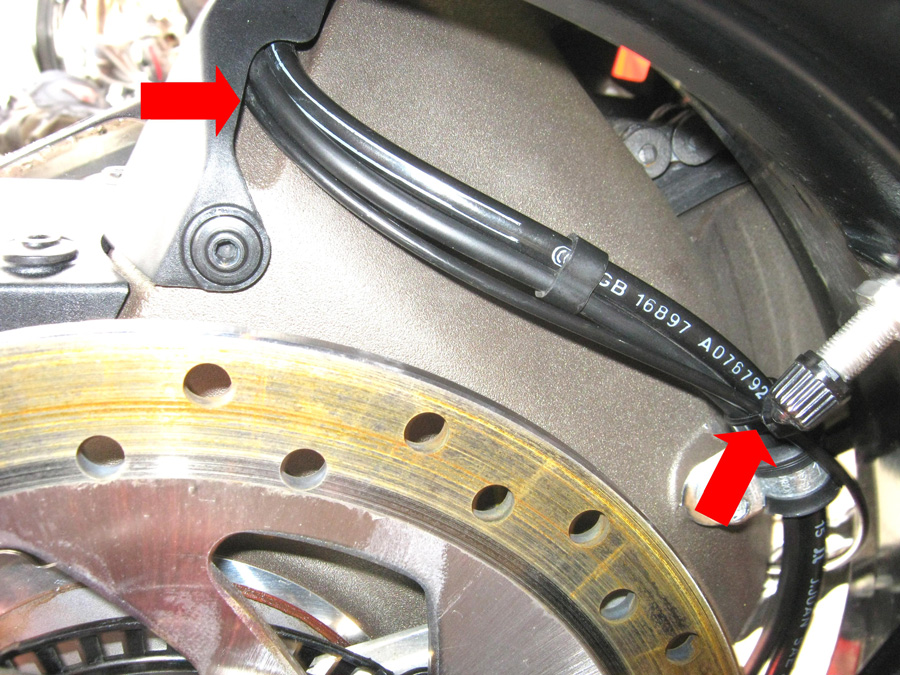 Use a long length of the black vacuum tubing as an alternative delivery tube. The smaller diameter of the black tubing will allow for it to be routed along existing break lines using existing cable routing gaps and fasteners.

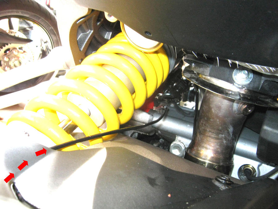
 Use the black vacuum tubing as delivery tubing all the way to the reservoir. The black tubing can then be connected to the clear delivery line that connects to the reservoir. To create a better seal mushroom the end of the black line in the flame of a lighter. Then push it into the clear delivery tube.
Step 4 - Fill, prime and set up your vSystem
Once fitted, fill and prime the system and set the adjuster knob to ’prime’. Start the engine and turn the adjuster knob until a flow of between 1 and 2 drops per minute is achieved. Check the condition of your chain after a ride, and then adjust as required.
For best results clean your chain before fitting the Scottoiler using paraffin or similar. Then lightly oil the chain from the bottle using a rag or a brush, this allows the oil from the Scottoiler to reach both sides of the chain. 1 to 2 drops per minute will maintain this film of oil on the chain.
xSystem Installation
The picture below is the xSystem 1.0 with the check valve in the delivery tubing, the xSystem 2.0 does not need the check valve.
Step 1 - Find a space for the reservoir
Step 2
Use a long length of the black vacuum tubing as an alternative delivery tube. The smaller diameter of the black tubing will allow for it to be routed along existing break lines using existing cable routing gaps and fasteners.

Step 3 - Position Dispenser
A dispenser can be made from vacuum tubing using the small dispenser plate and clip. The tubing can be routed with the rear brake line. For further information see our easy step installation guide - Dispenser Positioning. The curved nib should feed the outside face of the sprocket, with the slash cut facing outwards.
Step 4 - connect to battery
The xSystem must be wired directly to the battery. Attach the red wire to the +ve terminal and attach the black wire to the -ve terminal.
Slightly loosen the battery terminal screws to slip in the spade connectors.
Step 5 - Fill and prime system
Identify a desired location for the check valve in the delivery line. The location of the check valve can be anywhere along the delivery line and should be protected from outside elements. Fill the reservoir and prime the pump until oil reaches your desired check valve location. Cut and insert the check valve with the arrow facing in the direction of the oil flow. Repeat priming the pump until oil reaches the sprocket.
Step 6 - Set the flow rate
To turn the system on, press and hold the on/off button (at the bottom) until the LEDs light from the bottom , upwards. It will settle on the chosen flow rate.
To turn off, again, hold the on/off button and the LEDs will light up and turn off, one by one, downwards.
To increase the flow rate, make sure it’s switched on and press the upwards pointing arrow and the LED will move one position higher.
To reduce the flow rate, press the downward pointing arrow.
Set the flow rate on the middle section and adjust if required up/down depending on your riding conditions.
The xSystem will automatically switch on/off and no manual activation is necessary. You can manually turn the system on/off if you transport the motorcycle on a ferry or trailer.
eSystem Installation
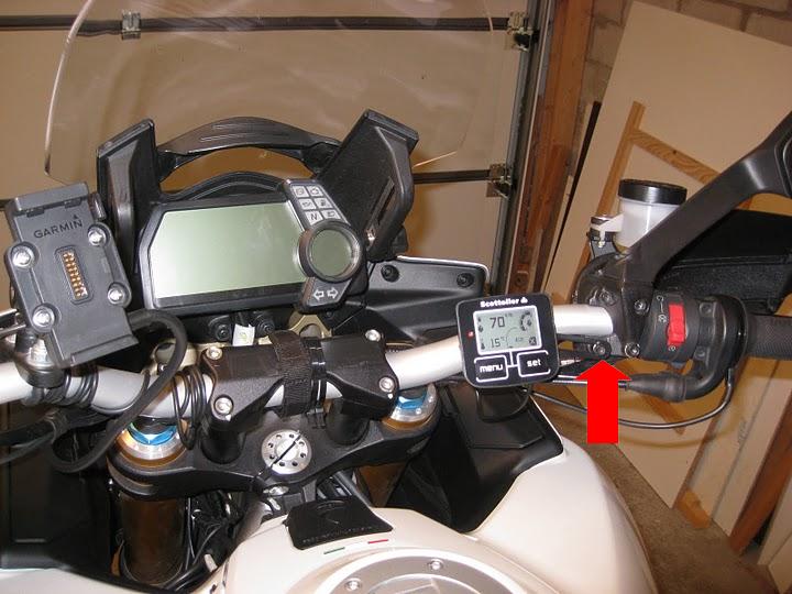
Step 1 - Find a place for the display
The Display Bracket (Part 5) can be rotated through 360° to give 4 mounting options and can also be flipped to provide 4 further options. The bracket can be secured to any M5/M6 bolt e.g. brake or clutch lever, brake cylinder or fairing mountings, in some cases you might need to trim the supplied bolt. It is possible to bend the bracket to shape, do so before fitting the Display Unit, part 1, to prevent damage to the unit. Alternatively, the sticky fasteners (Part 4) can be used to securely fasten the Display Unit to any flat surface e.g. the fork yokes.
Step 2 - Find a space for the reservoir
The reservoir can be mounted to the frame. The more vertical the reservoir is mounted the better. Avoid positioning the reservoir completely horizontally, as this will limit the available range. Remember to avoid exhaust and engine components. For further information, see our easy step installation guide – Reservoir Positions.
Step 3 - Mount dispenser on your rear sprocket
A dispenser can be made from vacuum tubing using the small dispenser plate and clip. The tubing can be routed with the rear brake line. For further information see our easy step installation guide - Dispenser Positioning. The curved nib should feed the outside face of the sprocket, with the slash cut facing outwards.
![]()
Step 4 - Connect to the battery
The eSystem must be wired directly to the battery. Attach the red wire to the +ve terminal and attach the black wire to the -ve terminal.
If you want to learn more about the eSystem Battery Connection and Power Consumption please click here.
Step 5 - Fill, prime, and set up your new eSystem
Once fitted, fill the REP and prime the pump. Attach the delivery tubing and prime until the oil reaches the point where you want to install the check valve. Stop the priming process and cut and insert the check valve at the chosen position. Continue priming the system until oil reaches the sprocket.
For further information you can also watch our installation video that shows the setup steps. How to fill and prime my eSystem?
Set the flow rate, using the ’Driving Screen’ on the Display Unit, to 60-70 seconds per drop (s/dp), check the condition of your chain after a ride, and adjust as required.
