Scottoiler Support Centre
Enter your motorcycle make and model to learn more about how to install a Scottoiler chain oiler system on your bike:

CRC-SO-5000BMW S1000XR Adapter Kit

 
3rd Party Adapter

CRC-SO-5000BMW is a third-party adapter set for fitting the xSystem to the BMW S1000XR models. It uses a novel approach to clamp the Scorpion Dual Injector in place and offers additional parts for route tubing and reservoir location under the seat.  


BMW S1000XR

Scottoiler step-by-step fitting instructions

Preparation

  • Tools needed: T25 & T40 Torx drivers
  •  Drill with 10.5mm and 2.0mm bits
  • Crosshead screwdriver.

    Note:
     References to "Parts" refer to the standard Scott oiler kit.


Phase 1: Disassembly & Access


  1.  Remove the seat.
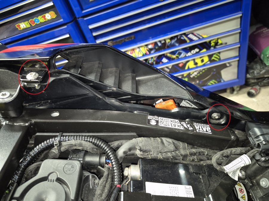
  2. Remove the left-hand side panel by unscrewing the two T25 Torx bolts.   (Picture 1)
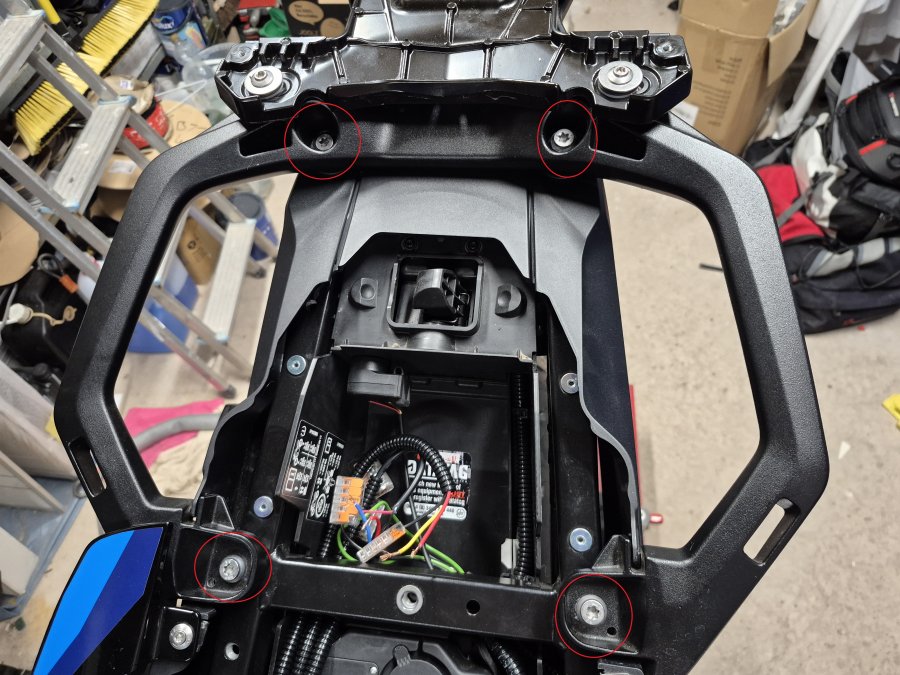
  3.  Detach the grab rail by removing the four T40 bolts securing it to the subframe. (See Picture 2)
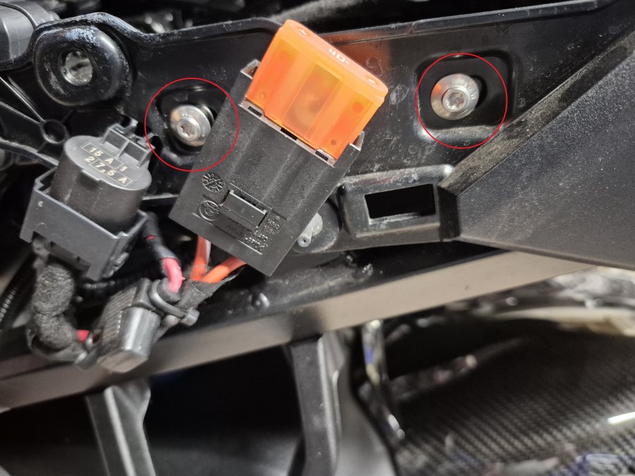
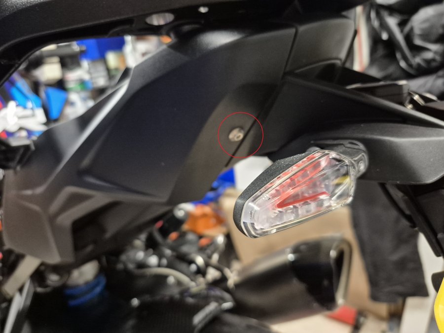
  4.  Remove the subframe cover by unscrewing the three T25 Torx bolts and carefully unclipping the three electrical connectors. (See Pictures 3 & 4)


Phase 2: Reservoir & Main Routing


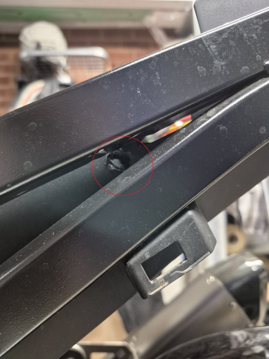
  1.  Drill a 10.5mm hole into the plastic between the two subframe bars. 
    CAUTION: Manually move the wiring behind the plastic out of the way before drilling. (See Picture 5)
  2.  Assemble the pipework: Feed the clear plastic pipe into the black corrugated   protective pipe.
  3.  Connect the reservoir: Feed the pipe assembly through the drilled hole. Attach Part 15 (adapter) to the clear pipe, then connect it to Part 1 (Reservoir).
  4.  Mount the locking base: Secure Part 2 (Locking Base) to Part 1B (Storage Unit) using two M5 x 22mm bolts, washers, and Nyloc nuts. 
    Tip: Test-fit the reservoir first to ensure the base is facing the correct way up.
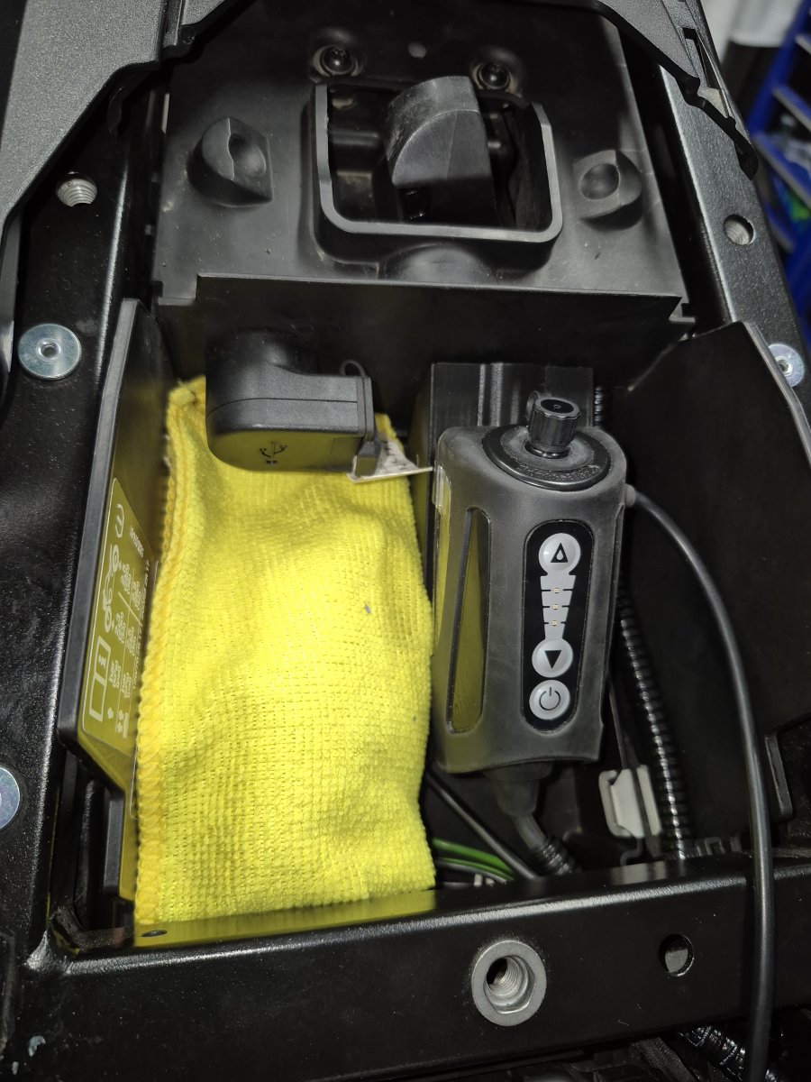
  5. Secure the storage compartment: Peel the backing from the double-sided tape and firmly press the unit to the left side of the compartment. (See Picture 6)
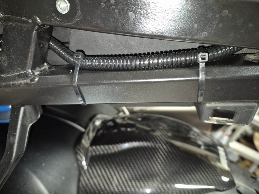
  6.  Route the piping: Feed the pipework down the subframe and secure it using cable ties. (See Picture 7)


Phase 3: Swingarm & Feed Pipe Installation


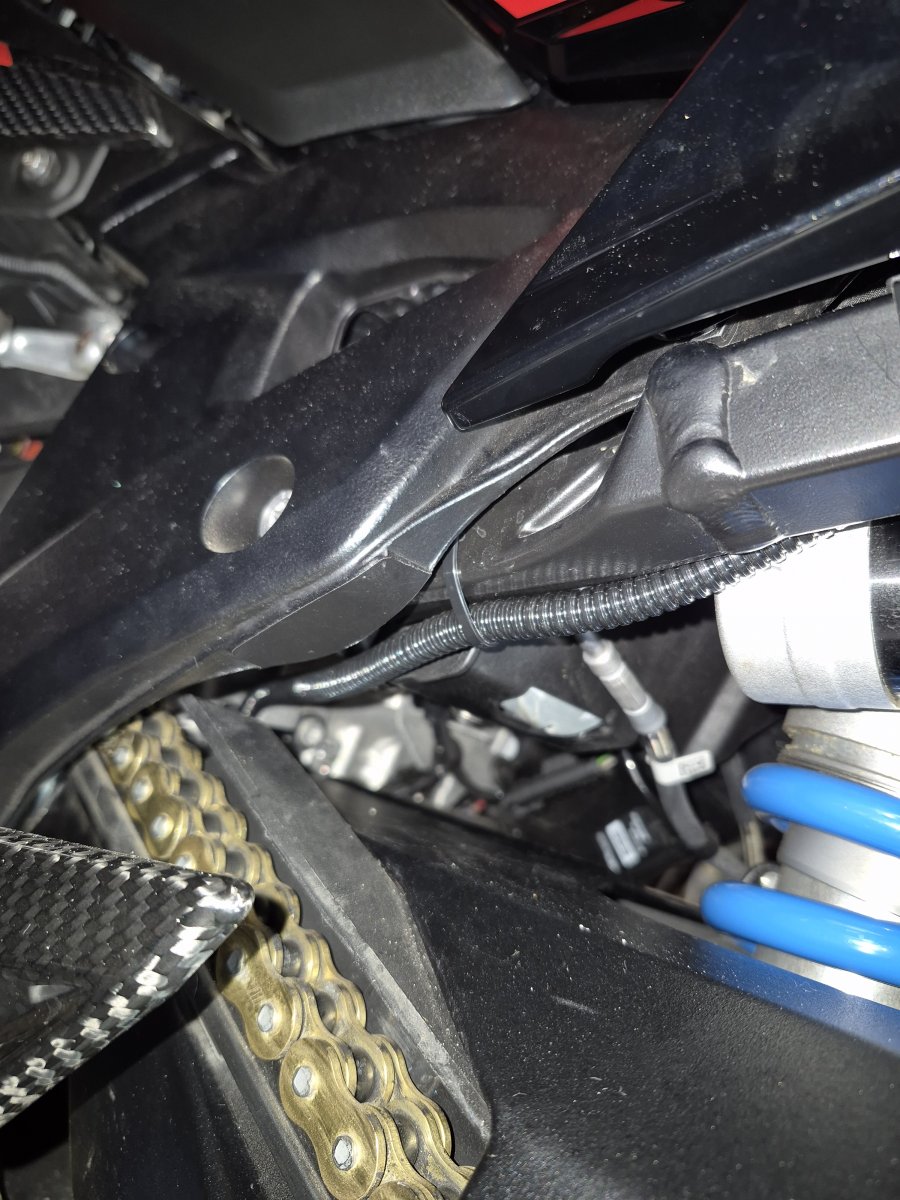
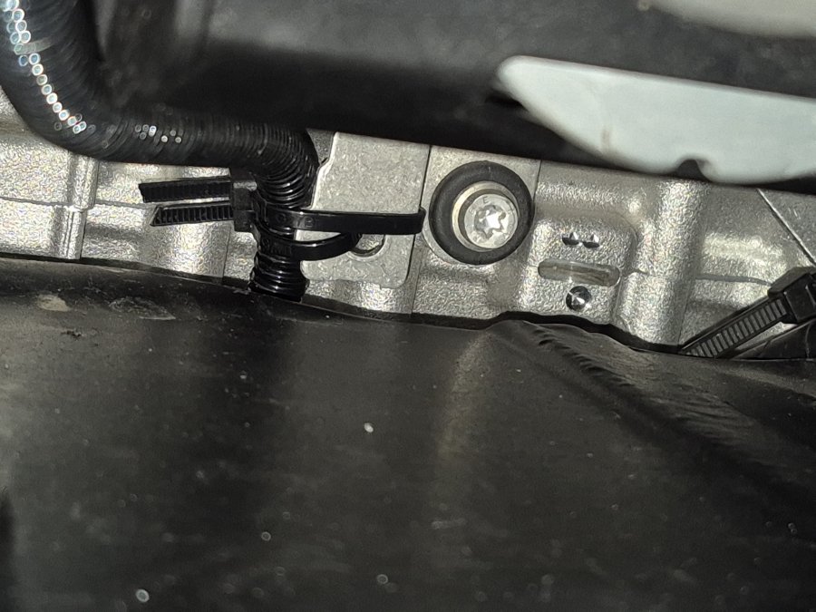
  1. Route to the swingarm: Run the pipe toward the swingarm and secure with cable ties. (See Picture 8 and 9)
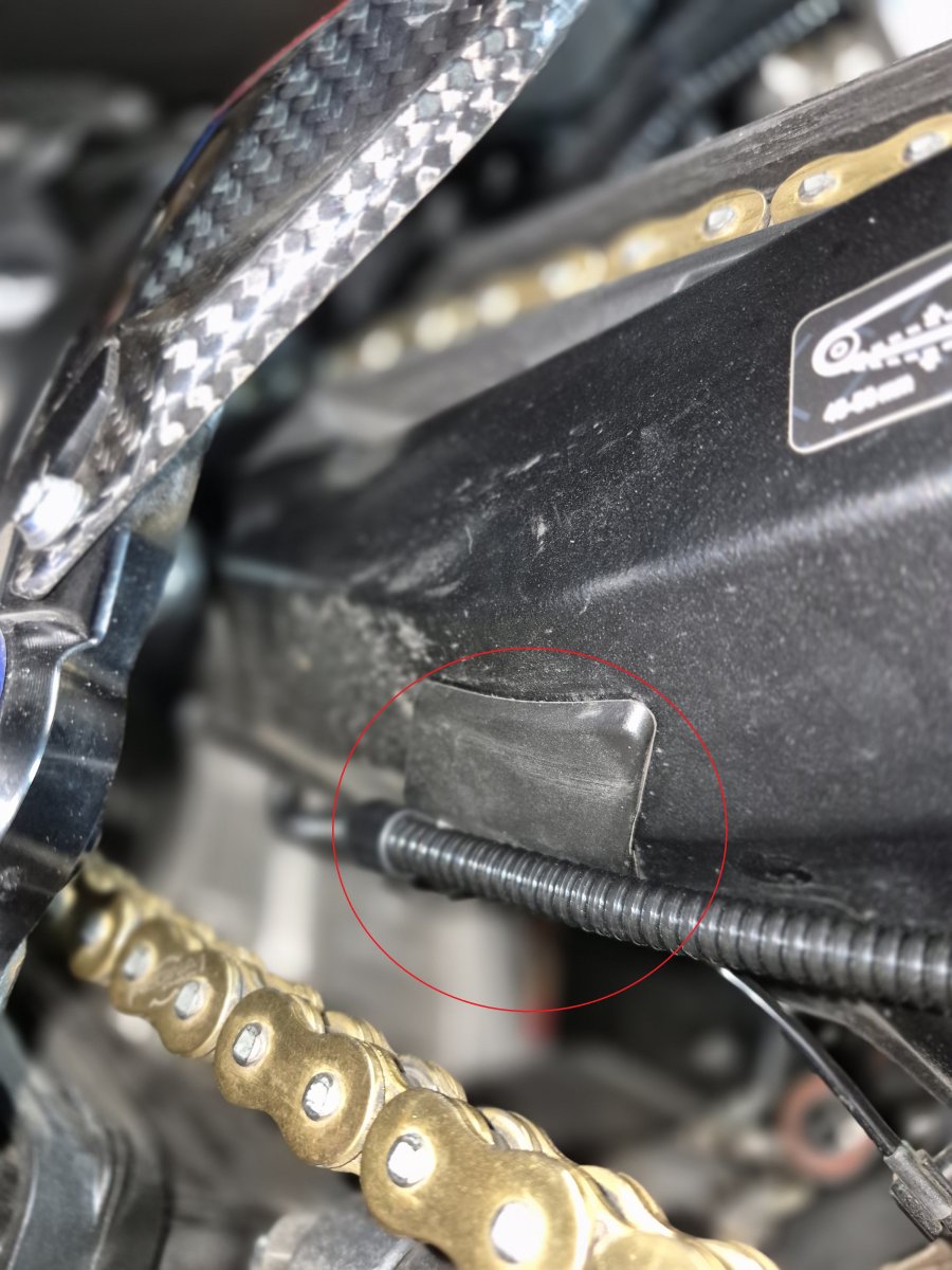
  2. Prepare the swingarm cover:
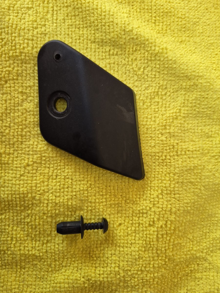
    1. Remove the plastic cover (secured by one crosshead screw).
    2.  Locate the plastic pin next to the screw hole and drill a 1.5mm hole into it.
    3. Reinstall the cover.
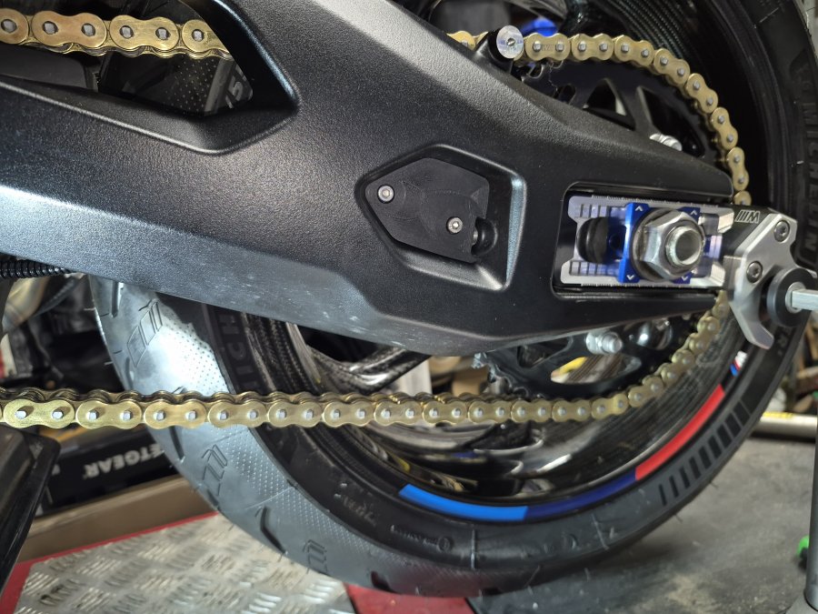
  3.   Secure the feed pipe: Place the supplied P-clip around the feed pipe and screw it into the newly drilled 2.0 mm hole using the provided crosshead screw. (See Picture 10)
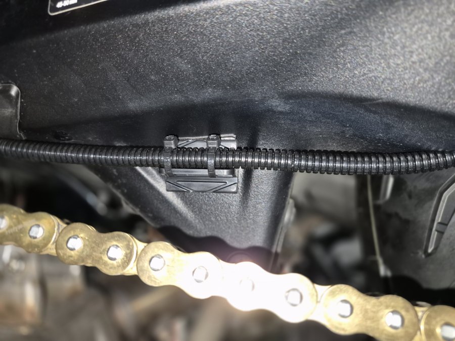
  4.  Mount the tab: Clean the area with the provided wipe. Attach Part 11 (Mounting Tab) and secure the feed pipe to it with two cable ties. (See Picture 11)


Phase 4: Final Assembly & Alignment


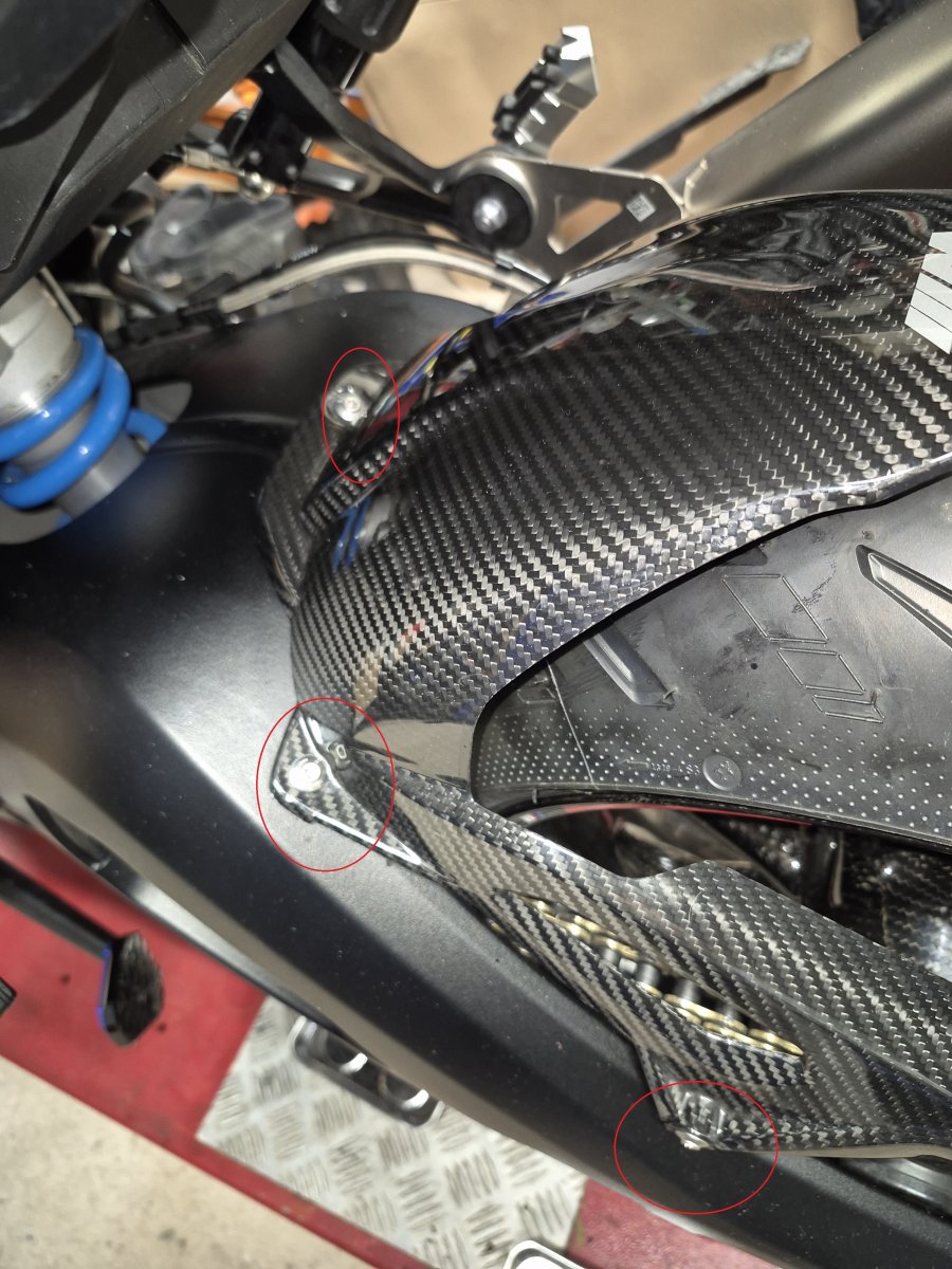
  1.  Access the inner swingarm: Remove the four T25 Torx bolts from the rear hugger. (See Picture 12)
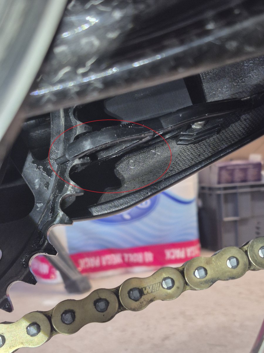
  2.  Install the rear plate: Insert an M5 x 20mm bolt through the rear hole of Part 2B (Swingarm Unit), pass it through the swingarm, and secure Part 3B (Rear Plate) with a washer and Nyloc nut. (See Picture 13)
  3.  Mount the Scorpion Feeder:
  1. Insert an M5 x 45mm bolt through the front hole of the unit, through the rear plate, and then through the Scorpion chain feeder.
  2. Secure with a washer and Nyloc nut.
    WARNING: Do not overtighten, as this will damage the Scorpion feeder. 
  3. Final Connection: Cut the oil feeder pipe to the required length and attach it firmly to the Scorpion feeder.


Final Check & Setup


Once physical installation is complete, follow the steps to activate and verify the system on the Scott oiler instalation manual


    Attachments
    There are no attachments for this article.